
SFP56-25/50GBase-CR1-xxM-FL Quick Spec:
Part Number: SFP56-25/50GBase-CR1-0.5M-FL
SFP56-25/50GBase-CR1-1M-FL SFP56-25/50GBase-CR1-1.5M-FL SFP56-25/50GBase-CR1-2M-FL SFP56-25/50GBase-CR1-2.5M-FL SFP56-25/50GBase-CR1-3M-FL SFP56-25/50GBase-CR1-4M-FL SFP56-25/50GBase-CR1-5M-FL
Form Factor: SFP56-SFP56 Cable Type: Twinax (DAC)
Rate Category: 25/50GBase-25/50GBase
Length: 0.5m, 1m, 1.5m, 2m, 2.5m,3m, 4m, 5m Active/Passive: Passive
SFP56-25/50GBase-CR1-xM-FL Features
Up to 56 GBbps bi-directional data links
Compliant with SFF-8402, IEEE802.3.bj, IEEE802.3cd
AC coupled inputs and outputs
100 Ohm differential impedance
All-metal housing for superior EMI performance
RoHS Compliance
Operating case temperature range: 0 to 70 deg C
SFP56-25/50GBase-CR1-xM-FL Applications
28G/56G Ethernet
High performance computing interconnect (switch, router, concentrator, Data Center)
Product Description
The FluxLight’s SFP56-25/50GBase-CR1-xM-FL is based on the same shape of SFP+, supports 28G/56G Ethernet standard, can provide 25Gb/s NRZ and 56Gb/s PAM-4 without error code transmission, and can be applied in high-density 28G/56G Ethernet switches and network interfaces to promote server connection in data centers. It uses today's popular SFP+ packaging to provide a more cost effective solution for enterprises to upgrade their 10G Ethernet connections.
Recommended Operating Conditions
Item | Requirement | Test Condition |
Operating Temp. Range | -20°C to +75°C | Cable operating temperature range. |
Storage Temp. Range (in packed condition) | -40°C to +80°C | Cable storage temperature range in packed condition. |
Thermal Cycling Non-Powered | No evidence of physical damage | EIA-364-32D, Method A, -25 to 90C, 100 cycles, 15 min. dwells |
Salt Spraying | 48 hours salt spraying after shell corrosive area less than 5%. | EIA-364-26 |
Mixed Flowing Gas | Pass electrical tests per 3.1 after stressing. (For connector only) | EIA-364-35 Class II,14 days. |
Temp. Life | No evidence of physical damage | EIA-364-17C w/ RH, Damp heat 90℃ at 85% RH for 500 hours then return to ambient |
Cable Cold Bend | 4H,No evidence of physical damage | Condition: -20℃±2℃, mandrel diameter is 6 times the cable diameter. |
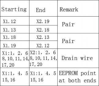
Pin Assignment and Description
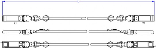
Mechanical Dimensions
Mechanical and Physical Characteristics
ITEM | REQUIREMENT | TEST CONDITON |
Vibration | Pass electrical tests per 3.1 after stressing. | Clamp & vibrate per EIA-364-28E, TC-VII, test condition letter – D, 15 minutes in X, Y & Z axis. |
Cable Flex | No evidence of physical damage | Flex cable 180° for 20 cycles (±90° from nominal position) at 12 cycles per minute with a 1.0kg load applied to the cable jacket. Flex in the boot area 90º in each direction from vertical. Per EIA-364-41C |
Cable Plug Retention in Cage | 90N Min. No evidence of physical damage | Force to be applied axially with no damage to cage. Per SFF 8661 Rev 2.1 Pull on cable jacket approximately 1 ft behind cable plug. No functional damage to cable plug below 90N. Per SFF-8432 Rev 5.0 |
Cable Retention in Plug | 90N Min. No evidence of physical damage | Cable plug is fixtured with the bulk cable hanging vertically. A 90N axial load is applied (gradually) to the cable jacket and held for 1 minute. Per EIA-364-38B |
Mechanical Shock | Pass electrical tests Per 3.1 after stressing. | Clamp and shock per EIA-364-27B, TC-G,3 times in 6 directions, 100g, 6ms. |
Cable Plug Insertion | 18N Max.(SFP28) | Per SFF-8432 Rev 5.0 |
Cable plug Extraction | 12.5N Max. (SFP28) | Measure without the aid of any cage kick-out springs. Place axial load on de-latch to de- latch plug. Per SFF-8432 Rev 5.0 |
Durability | 50 cycles,No evidence of physical damage | EIA-364-09, perform plug &unplug cycles:Plug and receptacle mate rate: 250times/hour. 50times for QSFP28/SFP28 module (CONNECTOR TO PCB) |
Electrical Performance
ITEM | REQUIREMENT | (TEST CONDITION) | ||||||
(Differen tial Impedanc e) | Cable Impedance | 105+5/-10Ω | Rise time of 25ps (20 % - 80 %). | |||||
Paddle Card Impedance | 100±10Ω | |||||||
Cable Termination Impedance | 100±15Ω | |||||||
[Differential (Input/Output)Return loss SDD11/SDD22] |
Return_loss(f)≥ 16.5-2√f 0.05≤f﹤4.1 Where 10.66-14log10(f/ 5.5) 4.1≤f≤19 f is the frequency in GHz Return loss(f) is the return loss at frequency f | 10MHz≤f ≤19GHz | ||||||
[Differential to common- mode (Input/Output)Return loss SCD11/SCD22] |
Return_loss(f)≥ 22-(20/25.78)f 0.01≤f﹤12.89 Where 15-(6/25.78)f 12.89≤f≤19 f is the frequency in GHz Return_loss(f) is the Differential to common-mode return loss at frequency f | 10MHz≤f ≤19GHz | ||||||
Common-mode to Common-mode (Input/Output)Return loss SCC11/SCC22 | Return_loss(f)≥2dB 0.2≤f≤19 Where f is the frequency in GHz Return_loss(f) is the common-mode to common-mode return loss at frequency f | 10MHz≤f ≤19GHz | ||||||
Differential Insertion Loss (SDD21 Max.) | (Differential InsertionLoss Max. For TPa to TPb Excluding Test fixture ) | 10MHz≤f ≤19GHz | ||||||
F AWG | 1.25G Hz | 2.5GH z | 5.0GH z | 7.0GH z | 10Ghz | 12.89Gh z | ||
30(1 m)M ax. | 4.5dB | 5.4dB | 6.3dB | 7.5dB | 8.5dB | 10.5dB | ||
30/2 8(3m )Max . | 7.5dB | 9.5dB | 12.2dB | 14.8dB | 18.0dB | 21.5dB | ||
26(3 m)M ax. | 5.7dB | 7.2dB | 9.9 dB | 11.9dB | 14.1dB | 16.5d B | ||
26/2 5(5m )Max . | 7.8dB | 10.0dB | 13.5dB | 16.0dB | 19.0dB | 22.0dB | ||
Differential to common- mode Conversion Loss- Differential Insertion Loss(SCD21-SDD21) | Conversion _loss(f) – IL(f)≥ 10 0.01≤f﹤
12.89 Where f is the frequency in GHz Conversion_loss(f ) is the cable assembly differential to common-mode conversion loss IL(f) is the cable assembly insertion loss | 10MHz≤f ≤19GHz |
MDNEXT(multiple disturber near-end crosstalk) | ≥26dB @12.89GHz | 10MHz≤f ≤19GHz |
Intra Skew | 15ps/m, | 10MHz≤f ≤19GHz |
Low Level Contact Resistance | 70milliohms Max. From initial. | EIA-364- 23:Apply a maximum voltage of 20mV And a current of 100 mA. |
Insulation Resistance | 10Mohm(Min.) | EIA364-21:AC 300V 1minute |
Dielectric Withstanding Voltage | NO disruptive discharge. | EIA-364- 20:Apply a voltage of 300 VDC for 1minute between adjacent terminals And between adjacent terminals and ground. |