
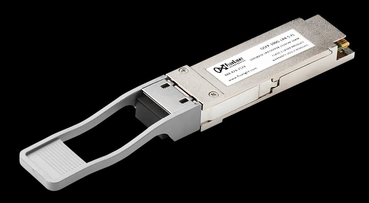


NVIDIA Compatible
MMS4X50-NM-FL
800G · OSFP · 1271–1331nmSMF · 2km · 2× Duplex LC
$1,299.99
MMS4X50-NM-FL, NVIDIA MMS4X50-NM-FL Compatible 800GBase-2FR4 OSFP112 1271/1291/1311/1331nm 2km DOM 2xDual-LC SMF Optical Transceiver Module Proudly Owned and Operated in the U.S.A. Since 2003
Need a larger quantity? Request a quote
Questions? Call (888) 874-7574
The OSFP-800G-2FR4-A-FL is an 800Gb/s Octal Small Form Factor Pluggable (OSFP112) optical module designed for 2km optical communication applications. The module converts 8 channels of 100Gb/s (PAM4) electrical input data to 8 optical signals, each of 100Gb/s. The 8 optical signals are composed of 2 groups of 4 CWDM wavelengths (1271nm, 1291nm, 1311nm, 1331nm). Each group of CWDM wavelengths are multiplexed into 2 optical outputs (1 Tx fiber in each of 2 Dual-LC connectors). Reversely, on the receiver side, the module demultiplexes 4 CWDM wavelengths, each of which is carrying 100Gb/s, from both Rx optical fibers in the 2 Dual-LC connectors and subsequently converts these into 8 channels of 100Gb/s (PAM4) electrical output data. The OSFP-800G02FR4-FL interoperates with either 2x 400G-FR4 OSFP/QSFPDD transceivers, or 2x 200G-FR4 QSFP transceivers.
| ApSel Code | Host Electrical Interface | Module Media Interface | Host and Media Lane Count | Host Lane Assignment |
|---|---|---|---|---|
| ApSel 1 | 50 (400GAUI-4-L C2M) | 1D (400GBASE-FR4) | 44 (4:4) | 11 (lanes 1,5) |
| ApSel 2 | 32 (IB NDR53G) | 1D (400GBASE-FR4) | 44 (4:4) | 11 (lanes 1,5) |
| ApSel 3 | 0F (200GAUI-4 C2M) | 18 (200GBASE-FR4) | 44 (4:4) | 11 (lanes 1,5) |
| ApSel 4 | 31 (IB HDR26G) | 18 (200GBASE-FR4) | 44 (4:4) | 11 (lanes 1,5) |
| ApSel 7 | 4F (400GAUI-4-S C2M) | 1D (400GBASE-FR4) | 44 (4:4) | 11 (lanes 1,5) |
| ApSel 10 | 42 (CAUI-4 C2M with RS FEC) | 10 (100G CWDM4 MSA) | 44 (4:4) | 11 (lanes 1,5) |
| ApSel 11 | 30 (IB EDR25G) | 10 (100G CWDM4 MSA) | 44 (4:4) | 11 (lanes 1,5) |
Table 1. CMIS Application Advertisements
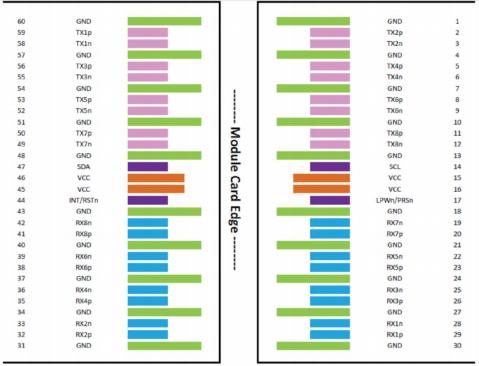
The electrical interface of the OSFP module consists of a 60-contact edge connector, as illustrated in Figure 1 and defined in Clause 8.1 of the OSFP MSA Specification.
| Pin# | Symbol | Description | Logic | Direction | Plug Sequence |
|---|---|---|---|---|---|
| 1 | GND | Ground | 1 | ||
| 2 | TX2p | Transmitter Data Non-Inverted | CML-I | Input from Host | 3 |
| 3 | TX2n | Transmitter Data Inverted | CML-I | Input from Host | 3 |
| 4 | GND | Ground | 1 | ||
| 5 | TX4p | Transmitter Data Non-Inverted | CML-I | Input from Host | 3 |
| 6 | TX4n | Transmitter Data Inverted | CML-I | Input from Host | 3 |
| 7 | GND | Ground | 1 | ||
| 8 | TX6p | Transmitter Data Non-Inverted | CML-I | Input from Host | 3 |
| 9 | TX6n | Transmitter Data Inverted | CML-I | Input from Host | 3 |
| 10 | GND | Ground | 1 | ||
| 11 | TX8p | Transmitter Data Non-Inverted | CML-I | Input from Host | 3 |
| 12 | TX8n | Transmitter Data Inverted | CML-I | Input from Host | 3 |
| 13 | GND | Ground | 1 | ||
| 14 | SCL | 2-wire Serial interface clock | LVCMOS-I/O | Bi-directional | 3 |
| 15 | VCC | +3.3V Power | Power from Host | 2 | |
| 16 | VCC | +3.3V Power | Power from Host | 2 | |
| 17 | LPWn/PRSn | Low-Power Mode / Module Present | Multi-Level | Bi-directional | 3 |
| 18 | GND | Ground | 1 | ||
| 19 | RX7n | Receiver Data Inverted | CML-O | Output to Host | 3 |
| 20 | RX7p | Receiver Data Non-Inverted | CML-O | Output to Host | 3 |
| 21 | GND | Ground | 1 | ||
| 22 | RX5n | Receiver Data Inverted | CML-O | Output to Host | 3 |
| 23 | RX5p | Receiver Data Non-Inverted | CML-O | Output to Host | 3 |
| 24 | GND | Ground | 1 | ||
| 25 | RX3n | Receiver Data Inverted | CML-O | Output to Host | 3 |
| 26 | RX3p | Receiver Data Non-Inverted | CML-O | Output to Host | 3 |
| 27 | GND | Ground | 1 | ||
| 28 | RX1n | Receiver Data Inverted | CML-O | Output to Host | 3 |
| 29 | RX1p | Receiver Data Non-Inverted | CML-O | Output to Host | 3 |
| 30 | GND | Ground | 1 | ||
| 31 | GND | Ground | 1 | ||
| 32 | RX2p | Receiver Data Non-Inverted | CML-O | Output to Host | 3 |
| 33 | RX2n | Receiver Data Inverted | CML-O | Output to Host | 3 |
| 34 | GND | Ground | 1 | ||
| 35 | RX4p | Receiver Data Non-Inverted | CML-O | Output to Host | 3 |
| 36 | RX4n | Receiver Data Inverted | CML-O | Output to Host | 3 |
| 37 | GND | Ground | 1 | ||
| 38 | RX6p | Receiver Data Non-Inverted | CML-O | Output to Host | 3 |
| 39 | RX6n | Receiver Data Inverted | CML-O | Output to Host | 3 |
| 40 | GND | Ground | 1 | ||
| 41 | RX8p | Receiver Data Non-Inverted | CML-O | Output to Host | 3 |
| 42 | RX8n | Receiver Data Inverted | CML-O | Output to Host | 3 |
| 43 | GND | Ground | 1 | ||
| 44 | INT/RSTn | Module Interrupt / Module Reset | Multi-Level | Bi-directional | 3 |
| 45 | VCC | +3.3V Power | Power from Host | 2 | |
| 46 | VCC | +3.3V Power | Power from Host | 2 | |
| 47 | SDA | 2-wire Serial interface data | LVCMOS-I/O | Bi-directional | 3 |
| 48 | GND | Ground | 1 | ||
| 49 | TX7n | Transmitter Data Inverted | CML-I | Input from Host | 3 |
| 50 | TX7p | Transmitter Data Non-Inverted | CML-I | Input from Host | 3 |
| 51 | GND | Ground | 1 | ||
| 52 | TX5n | Transmitter Data Inverted | CML-I | Input from Host | 3 |
| 53 | TX5p | Transmitter Data Non-Inverted | CML-I | Input from Host | 3 |
| 54 | GND | Ground | 1 | ||
| 55 | TX3n | Transmitter Data Inverted | CML-I | Input from Host | 3 |
| 56 | TX3p | Transmitter Data Non-Inverted | CML-I | Input from Host | 3 |
| 57 | GND | Ground | 1 | ||
| 58 | TX1n | Transmitter Data Inverted | CML-I | Input from Host | 3 |
| 59 | TX1p | Transmitter Data Non-Inverted | CML-I | Input from Host | 3 |
| 60 | GND | Ground | 1 |
Table 2. OSFP Connector Pin List
| Name | Direction | Description |
|---|---|---|
| SCL | BiDir | 2-wire serial clock signal. Requires pull-up resistor to 3.3V on host |
| SDA | BiDir | 2-wire serial data signal. Requires pull-up resistor to 3.3V on host. |
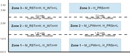
| LPWn/PRSn | Input/Output | Dual Function Signal. - Low Power mode is an active-low input signal. - Module Present is controlled by a pull-down resistor on the module which gets converted to an active-low output logic signal - Voltage zones are shown in Figure 2. |
| INT/RSTn | Input/Output | Dual Function Signal. - Reset is an active-low input signal. - Interrupt is an active-high output signal - Voltage zones are shown in Figure 2. |
Table 3. OSFP Control Pins
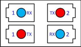
The optical interface port is dual duplex LC. The transmit and receive optical lanes shall occupy the positions depicted in Figure 4 when looking into the MDI receptacle with the connector keyway feature on top.
Operation in excess of any individual absolute maximum rating may cause permanent damage to the module.
| Parameter | Symbol | Min | Max | Units |
|---|---|---|---|---|
| Storage Temperature | TS | -40 | 85 | °C |
| Power Supply Voltage | VCC | -0.3 | 3.6 | V |
| Relative Humidity (non-condensation) | RH | 5 | 85 | % |
| Damage Power | Pmax | 5.7 | dBm | |
| ESD, electrical pins | ESD | -1 | 1 | kV |
| Parameter | Symbol | Min | Typical | Max | Units | Notes |
|---|---|---|---|---|---|---|
| Operating Case Temperature | TOP | 0 | 70 | °C | ||
| Power Supply Voltage | VCC | 3.135 | 3.3 | 3.465 | V | |
| Data Rate, each Lane | 53.125 | GBd | PAM4 | |||
| Data Rate Accuracy | -100 | 100 | ppm | |||
| Pre-FEC Bit Error Ratio | 2.4×10⁻⁴ | |||||
| Post-FEC Bit Error Ratio | 1×10⁻¹⁵ | 1 | ||||
| Link Distance | D | 0.002 | 2 | km | 2 |
The following electrical characteristics are defined over the Recommended Operating Environment unless otherwise specified.
| Parameter | Test Point | Min | Typical | Max | Units |
|---|---|---|---|---|---|
| Power Consumption | 15 | W | |||
| Supply Current | Icc | 4.5 | A | ||
| Module Input (each Lane) | |||||
| Signaling Rate, each Lane | TP1 | 53.125 ± 100 ppm | GBd | ||
| DC Common-mode input Voltage | TP1 | -0.35 | 2.85 | V | |
| Single-ended input Voltage | TP1a | -0.4 | 3.3 | V | |
| AC Common-mode RMS input Voltage Low-frequency, VCMLF Full-Band, VCMFB | TP1a | 32 80 | mV | ||
| Module stressed input test | IEEE 802.3ck 120G3.4.3 | ||||
| Differential Peak-to-Peak input Voltage tolerance | TP1a | 750 | mV | ||
| Common-mode to Differential-mode Input Return Loss | TP1 | IEEE802.3ck Equation 120G-2 | |||
| Effective input Return Loss | TP1 | 8.5 | dB | ||
| Differential input Termination Mismatch | TP1 | 10 | % | ||
| Module Output (each Lane) | |||||
| Signaling Rate, each lane | TP4 | 53.125 ± 100 ppm | GBd | ||
| Differential Peak-to-Peak Output Voltage Short mode Long mode | TP4 | 600 845 | mV | ||
| AC Common Mode Output Voltage, RMS Low-frequency, VCMLF Full-Band, VCMFB | TP4 | 32 80 | mV | ||
| Differential Termination Mismatch | TP4 | 10 | % | ||
| Eye height | TP4 | 15 | mV | ||
| Vertical eye closure, VEC | TP4 | 12 | dB | ||
| Common-mode to Differential-mode Output Return Loss | TP4 | IEEE802.3ck Equation 120G-1 | dB | ||
| Effective output Return Loss | TP4 | 8.5 | dB | ||
| Output Transition time (20% to 80%) | TP4 | 8.5 | ps | ||
| DC Common-mode output Voltage | TP4 | -350 | 2850 | mV | |
| Parameter | Symbol | Min | Typical | Max | Units | Notes |
|---|---|---|---|---|---|---|
| Wavelength Assignment | L0 | 1265.25 | 1271 | 1276.75 | nm | |
| L1 | 1285.25 | 1291 | 1296.75 | nm | ||
| L2 | 1305.25 | 1311 | 1316.75 | nm | ||
| L3 | 1325.25 | 1331 | 1336.75 | nm | ||
| L4 | 1265.25 | 1271 | 1276.75 | nm | ||
| L5 | 1285.25 | 1291 | 1296.75 | nm | ||
| L6 | 1305.25 | 1311 | 1316.75 | nm | ||
| L7 | 1325.25 | 1331 | 1336.75 | nm | ||
| Transmitter | ||||||
| Data Rate, each Lane | 53.125 ± 100 ppm | GBd | ||||
| Modulation Format | PAM4 | |||||
| Side-mode Suppression Ratio | SMSR | 30 | dB | |||
| Total average launch power | 9.5 | dBm | ||||
| Average Launch Power, each Lane | PAVG | -3.2 | 3.5 | dBm | 1 | |
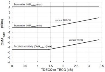
| Outer Optical Modulation Amplitude (OMAouter), each Lane | POMA | Max(−0.2, −1.6+TDECQ) | 3.7 | dBm | 2 | |
| Difference in launch power between any two lanes (OMAouter) | 4 | dB | ||||
| Transmitter and Dispersion Eye Closure for PAM4 (TDECQ), each Lane | TDECQ | 3.4 | dB | |||
| Transmitter eye closure for PAM4 (TECQ), each Lane | TECQ | 3.4 | dB | |||
| |TDECQ-TECQ| | 2.5 | dB | ||||
| Over/under-shoot | 22 | % | ||||
| Transmitter peak-to-peak power | 4.5 | dBm | ||||
| Extinction Ratio | ER | 3.5 | dB | |||
| RIN17.1OMA | RIN | -136 | dB/Hz | |||
| Optical Return Loss Tolerance | TOL | 17.1 | dB | |||
| Transmitter Reflectance | RT | -26 | dB | |||
| Transmitter Transition Time | 17 | ps | ||||
| Average Launch Power of OFF Transmitter, each Lane | Poff | -16 | dBm | |||
| Receiver | ||||||
| Data Rate, each Lane | 53.125 ± 100 ppm | GBd | ||||
| Modulation Format | PAM4 | |||||
| Damage Threshold, each Lane | THd | 4.5 | dBm | 3 | ||
| Average Receive Power, each Lane | -7.2 | 3.5 | dBm | 4 | ||
| Receive Power (OMAouter), each Lane | 3.7 | dBm | ||||
| Difference in receive power between any two lanes (OMAouter) | 4.1 | dB | ||||
| Receiver Sensitivity (OMAouter), each Lane | SEN | Equation (1) | dBm | 5 | ||
| Stressed Receiver Sensitivity (OMAouter), each Lane | SRS | -2.6 | dBm | 6 | ||
| Bit Error Ratio Floor | BER_FL | 3.4×10⁻⁶ | 7 | |||
| Receiver Reflectance | RR | -26 | dB | |||
| LOS Assert | LOSA | -16 | -13 | -10 | dBm | |
| LOS De-assert | LOSD | -15 | -11 | -7 | dBm | |
| LOS Hysteresis | LOSH | 1 | 2 | 3 | dB | |
| Conditions of Stress Receiver Sensitivity Test (Note 8) | ||||||
| Stressed Eye Closure for PAM4 (SECQ), Lane under Test | 3.4 | dB | ||||
| OMAouter of each aggressor lane | 1.5 | dBm | ||||
The following digital diagnostic characteristics are defined over the normal operating conditions unless otherwise specified.
| Parameter | Symbol | Min | Max | Units | Notes |
|---|---|---|---|---|---|
| Temperature monitor absolute error | DMI_Temp | -3 | 3 | °C | Over operating temperature range |
| Supply voltage monitor absolute error | DMI_VCC | -0.1 | 0.1 | V | Over full operating range |
| Channel RX power monitor absolute error | DMI_RX_Ch | -2 | 2 | dB | 1 |
| Channel bias current monitor absolute error | DMI_Ibias_Ch | -10 | 10 | % | |
| Channel TX power monitor absolute error | DMI_TX_Ch | -2 | 2 | dB | 1 |
This transceiver is specified as ESD threshold 1kV for high-speed data pins and 2kV for all other electrical input pins, tested per MIL-STD-883, Method 3015.4 /JESD22-A114-A (HBM). However, normal ESD precautions are still required during the handling of this module. This transceiver is shipped in ESD protective packaging. It should be removed from the packaging and handled only in an ESD protected environment.
This is a Class 1 Laser Product according to IEC/EN 60825-1:2014.
This product complies with 21 CFR 1040.10 and 1040.11 except for conformance with IEC 60825-1 Ed. 3., as described in Laser Notice No. 56, dated May 8, 2019.
Caution: Use of controls or adjustments or performance of procedures other than those specified herein may result in hazardous radiation exposure.
The FluxLight OSFP-800G-2FR4-A-FL is compatible with the Arista OSFP-800G-2FR4, which Arista certifies on all its platforms. It works in any Arista switch port that takes the OSFP-800G-2FR4, running EOS 4.29.2 or later.
The following is a list of Finisar Corporation patents Fluxlight has licensed. This licensure recognizes and compensates Finisar for their intellectual property. The OSFP-800G-2FR4-FL, like all Fluxlight optical transceivers, is covered by this license agreement. Therefore, Fluxlight customers can rest assured that all products purchased are fully licensed, and our customers are under no potential liability that may ensue from the use of unlicensed optical transceiver products.
U.S. Patent Numbers: 7,184,668 (System and method of protecting eye safety during operation of a fiber optic transceiver), 7,079,775 (Integrated memory mapped controller circuit for fiber optics transceiver), 6,957,021 (Optical transceiver with memory mapped locations), 7,058,310 (System and method for protecting eye safety during operation of a fiber optic transceiver), 6,952,531 (System and method for protecting eye safety during operation of a fiber optic transceiver), 7,162,160 (System and method for protecting eye safety during operation of a fiber optic transceiver), 7,050,720 (Integrated memory mapped controller circuit for fiber optics transceiver)
Original Equipment Manufacturer (OEM) names may be registered trademarks of the respective OEM, and the OEM has neither authorized nor sponsored the use of its trademark or trade name. All OEM names are used for cross reference/comparative purposes only.
This part is covered by our Limited Lifetime Warranty, a 10-year serviceable lifetime, and our 30-Day Money-Back Guarantee. Read the full warranty and return terms.
No reviews yet. If you have used this part, yours would be the first.
Get compatible transceivers and cables shipped fast, with expert support when you need it.


85 in stock
Order by 3 PM CT for same-day shipping


800G · OSFP · 1271–1331nmSMF · 2km · 2× Duplex LC

800G · OSFP · 1271–1331nmSMF · 2km · 2× Duplex LC

800G · OSFP · 1271–1331nmSMF · 10km · 2× Duplex LC

800G · OSFP · 1271–1331nmSMF · 10km · 2× Duplex LC